Perforation Data
Interactive
Well Site > Available Reports
Data
The Perforation form is used to record all aspects for
a perforation job from the initial well conditions to details for all
perforation intervals, including the total number of shots. A new Perforation
report must be created each time a perforation is performed on the Wellbore.
Recorded perforations are also added as Wellbore
Openings for the wellbore associated to the Perforation report. These,
in turn, may be associated to a completion. For a combined perforate and
gravel pack job, the Perforation report may be associated to a Gravel
Pack job.
Perforation data can be recorded from the surface and
Activities
link.
The Perforation report allows
the user to add, review, modify and delete the details of perforation
jobs on a daily basis.
Special Fields and Functions
This section defines buttons, calculated fields, read-only
fields, some drop-down picklists and other areas with special functionality.
Click a link to skip to the specified section.
Buttons
General
Intervals
Units
and Datums
Buttons
Update Time Summary Button
The Update Time Summary button
allows users to push data entered in specific reports directly into a
new row in the Time Summary spreadsheet. This button is configured in
the Layout Manager of the EDM Administration Utility. This button reduces
data entry time and duplication.
This feature is available
in the following areas:
Classic Entry
Form: Casing, Cementing, Perforation, Stimulations and Wellbore
Equipment,
When the Update
Time Summary button is selected in the OpenWells® application the
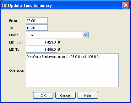
Update Time Summary dialog appears.
From this dialog the user
can verify the data is correct, edit if necessary or click OK
to push the data to the Time Summary spreadsheet.
The following sample shows
data pushed from a Perforation report to the Time Summary spreadsheet.


General
Perforated String
The Perforated
String picklist lists all casings, liners and assembly strings
that have been recorded for the wellbore. Select the specific casing,
liner, or assembly string which was perforated.
Note: Verify
that the correct perforated string has been selected from the picklist.
The item selected for this field will affect the Schematic drawn in the
PROFILE™application.
Hydrostatic Pressure
Hydrostatic
Pressure is calculated as a function of the Fluid
Density and TVD Reservoir
(Surface Pressure is also added to display effective Hydrostatic Press
(Hydrostatic Pressure) at TVD Reservoir).
Fluid Head
Fluid
Head = TVD Reservoir - TVD Fluid Top
Pressure Difference
Pressure Difference
= Hydrostatic Pressure - Estimate Reservoir Pressure
Underbalanced check box
The Underbalanced
check box is automatically checked if the Pressure
Difference field contains a negative value. This check box cannot
be modified.
Condition
The Condition
field is based on the calculated results found in the Pressure
Difference field. There are three possible entries:
Over Balanced (positive number in
Pressure Difference field)
— The Condition is Over
Balanced if the hydrostatic
pressure exerted by the wellbore fluid inside the casing or liner
is greater than the reservoir pressure. Once the perforation is
made, there will be a tendency for the wellbore fluid to flow
into the reservoir formation.
MD Top
The Measured
Depth (MD) Top of the shallowest shot that is entered in the Intervals
spreadsheet.
MD Base
The Measured
Depth (MD) Base of the deepest shot that is entered in the Intervals
spreadsheet.
Net Perforation Interval
The Net
Perforation Interval is calculated as the sum of the difference
between the MD Base less the MD Top for all intervals entered
in the Intervals spreadsheet.
Perforation Length Gross
The Gross
Perforation Length is calculated as the distance between the uppermost
and lowermost shots entered in the Intervals spreadsheet for the perforation
operation.
Total Shots
The Total
Shots field is the sum of the following calculation for all rows
in the Intervals spreadsheet.
Total Shots
= {SP/ (shot/ft) x [TS-BS (length)]} + Additional Shot - Misfires
Average Shot Density
The Average
Shot Density is calculated from the values in the Intervals spreadsheet.
Average
Shot Density = Total Shots / Net Perforation Interval
No. of Intervals
The Number
of Intervals is calculated from the shot intervals entered in the
Intervals spreadsheet.
Reference Log
Select the date and an associated reference
log from the picklist for the perforation job. This list is populated
from Log Suites (runs) created
in the Logging
report.
Intervals
Formation
Select a Formation
from the picklist. If the required Formation
is not available, additions can be made in the Formation tab of the Wellbore Properties dialog.
Reservoir
Select a Reservoir
(Zone) from the picklist. If the required Reservoir
is not available, additions can be made in the Reservoirs tab of the Project Properties dialog.
Misrun check box
If the Misrun
check box is activated in the Intervals spreadsheet, then the perforations
recorded for that row will not be included in calculations for Total
Shots and Average Shot Density
in the General section.
Details Link
The Details
link, located in the intervals spreadsheets, allows for further information
on the perforation interval rows to be recorded.
Units and Datums
Units Picklist 
The Unit Management System in the EDM™ database
controls display units in EDT™ applications. Every numerical element in
the EDM database has a storage measure (some known quantity in the physical
world) associated with it such as feet, ft/sec, or °F.
In OpenWells® software, Active Viewing Units
(or Display Units as they are sometimes referred to) are for presentation
purposes only. Display units can changed at any time and do not affect
the quality of the data.
Active Viewing Units for the OpenWells application
are selected from the Unit picklist
located at the top of each page.
Datum Selector 
The reference point for depths changes over
the life cycle of a Well, with changes in rigs and viewing data requirements.
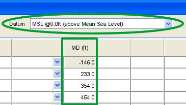
The Datum Selector, located at the top of
each page, allows users to change displayed the depth reference point
(datum) on the fly.
Changing the depth reference point displays
depths relative to the datum selected. This DOES NOT change the values
in the database itself.
Data MUST be
entered correctly in context to the selected datum reference point.
The following example shows how the viewing
datum affects the data you see.


Print Page 
The Print Page button allows users to print
the current page as it appears in the window.


